Machine NumberMachine Number
| Name | Type | Scope |
|---|---|---|
| Brick Lining Machine | QZJ10KT-1 | 4.8M–6.5M |
Working PrincipleWorking Principle
2.1、This equipment is purpose-built for the refractory brick lining of horizontal rotary kilns in modern cement plants. It is an upgraded product that incorporates and improves upon the advanced technology of similar machines. The entire machine is fabricated from high-strength aluminium alloy, which greatly reduces its weight and the operator's labour intensity during installation and adjustment while maintaining structural strength.
2.2、This machine is suitable for lining refractory bricks in horizontal rotary kilns with an inner diameter of 4.8–6.5 m.
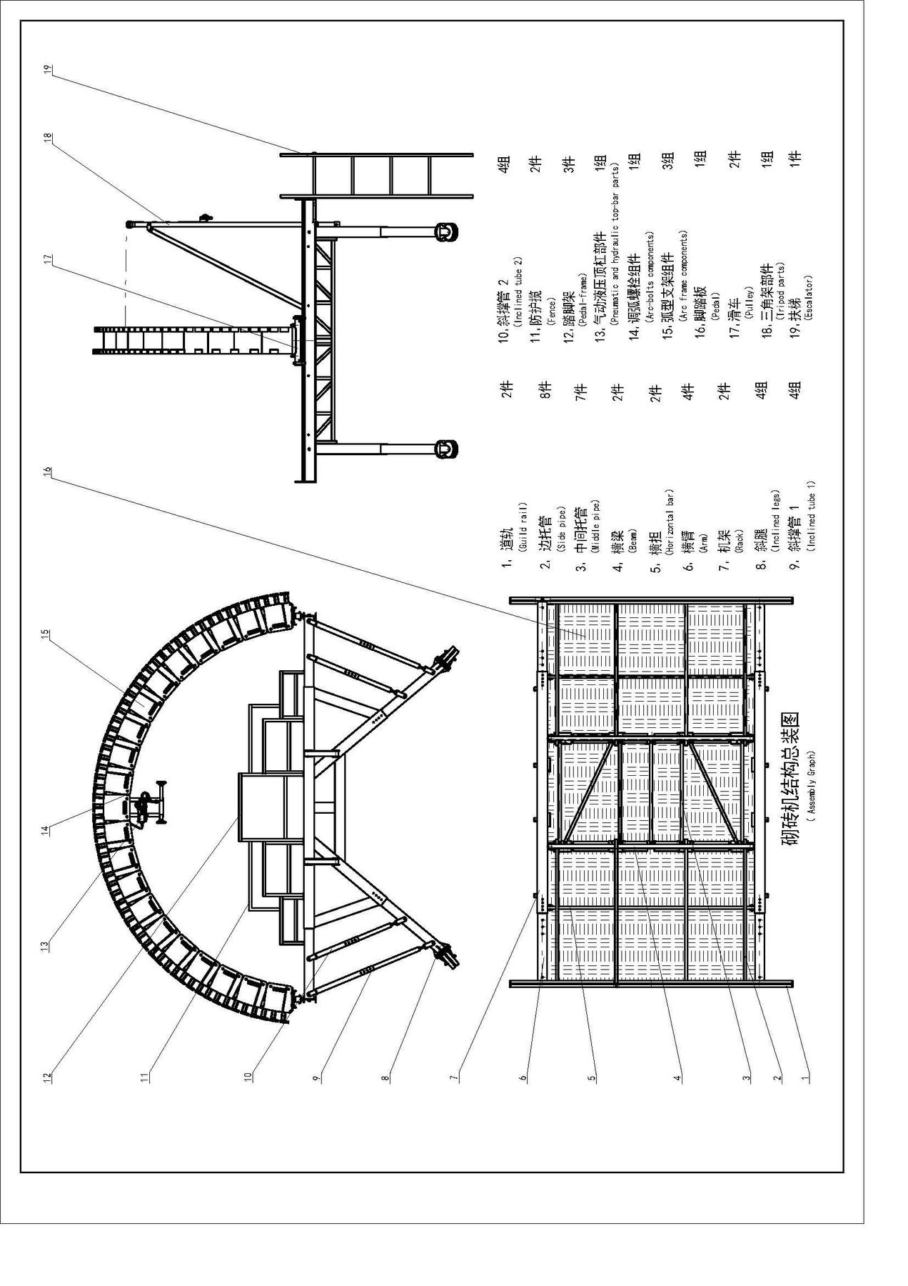
2.3、The equipment consists of the rack, running gear, adjustable arch frame, cylinders, pneumatic/hydraulic top bar assemblies and guide pulley assemblies (see the machine assembly drawing).
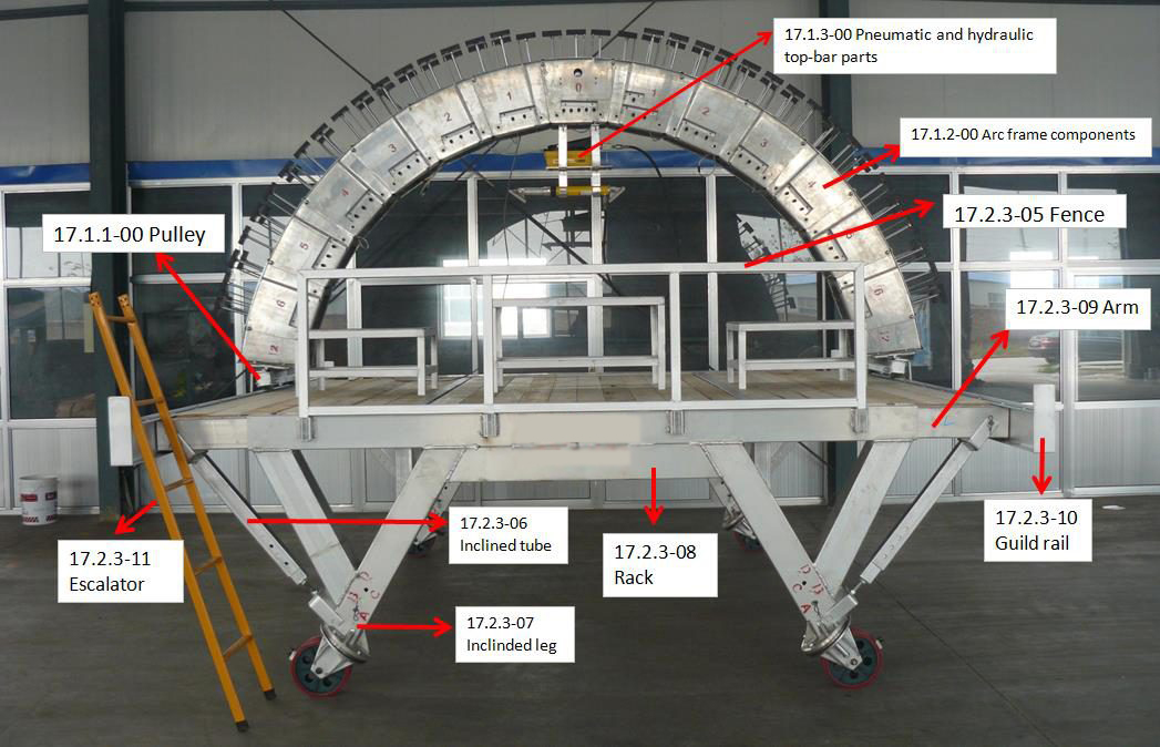
2.4、The machine is driven by compressed air. The air passes through the triplet oil–water separator (17.1.2-00-1) and the cylinder control valves to each cylinder, completing the cylinder extension and retraction cycles.
2.5、The machine is equipped with an air pressure protection device (with a built-in accumulator), which prevents the air pressure from dropping rapidly after the air supply is cut off.
Technical DataTechnical Data
| Model | Dimension | Work pressure | Work stroke | Pump stroke |
|---|---|---|---|---|
| QZJ10KT-1 | 4200×5110×4400 | 0.4–0.6 MPa | 3500 mm | 150 mm |
Hydraulic Pump
| Model | Work pressure | Flow | Noises | Weight |
|---|---|---|---|---|
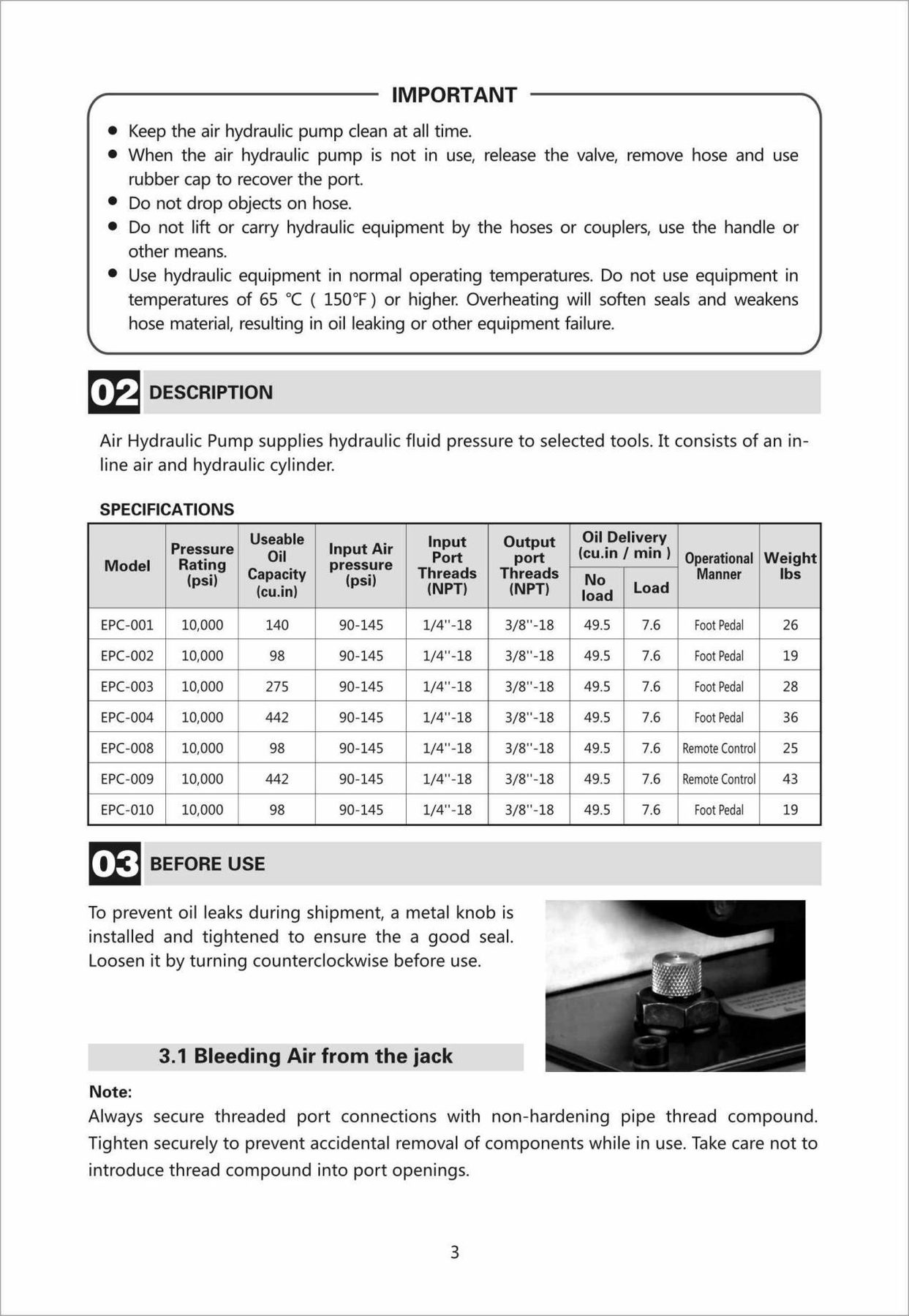
| EPC002 | 0.4–0.6 MPa | 40 cu.in/min | 85 dBA | 8.6 kg |
Hydraulic Cylinder
| Model | Stroke | Work pressure | Bearing capacity | Weight |
|---|---|---|---|---|
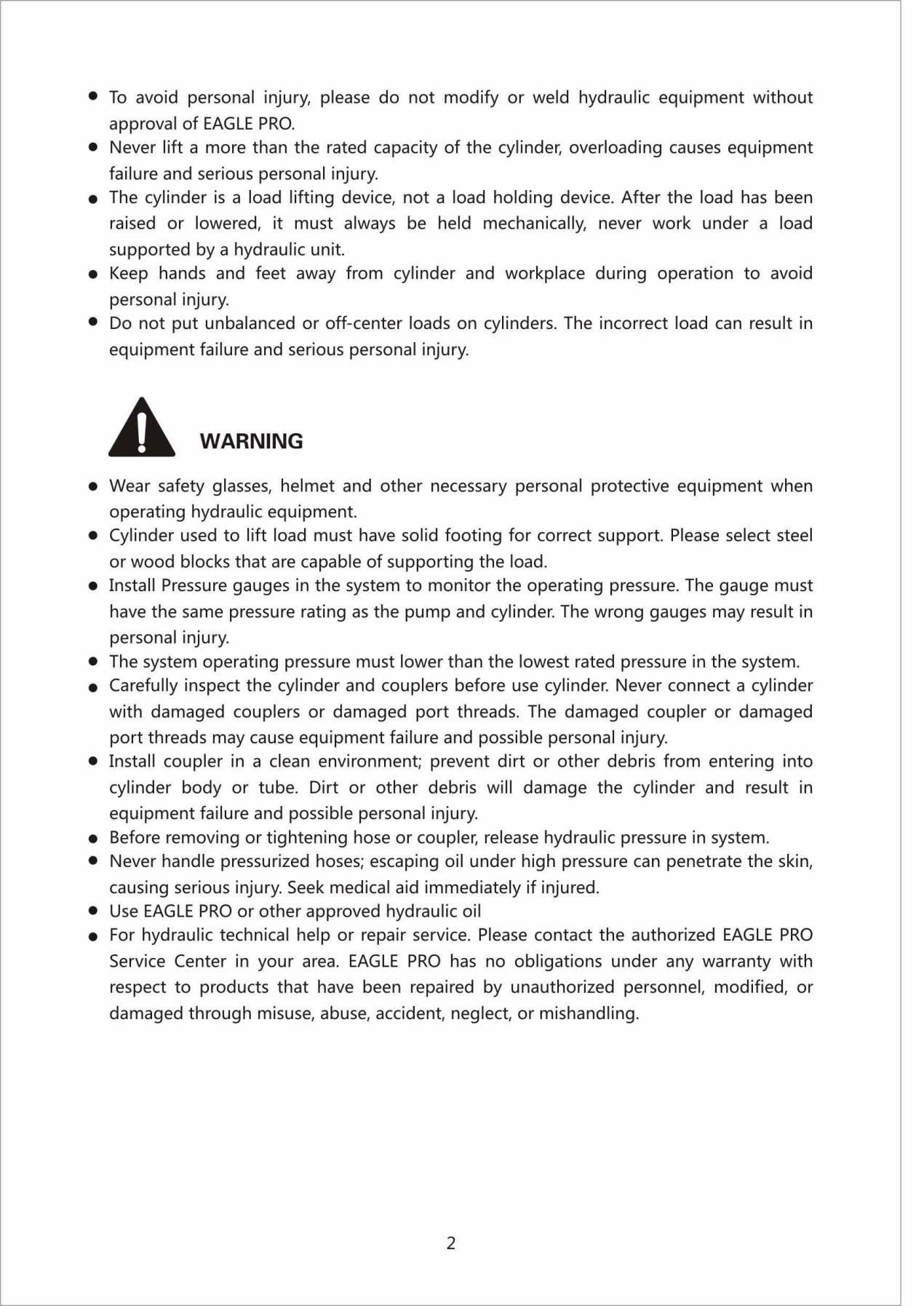
| ES1014 | 356 mm | 0–30 MPa | 10 t | 7.2 kg |
Air Compressor (NOTE: Supplied by the Operator)
| Model | Speed | Max. Pressure | Gas Storage | Weight |
|---|---|---|---|---|
| W-0.90/8/HM | 950 R.P.M | 8 Bar | 170 L / 44.9 Gal | 193 kg |
AssemblyAssembly
4.1、Machine frame assembly
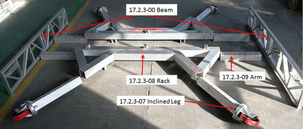
| Item No. | Name | Spec. | Unit | QTY | Note |
|---|---|---|---|---|---|
| 17.2.3-00 | Beam | 3000*470mm | Pcs | 2 | |
| 17.2.3-07 | Inclined Leg | L=1200mm | Groups | 4 | |
| 17.2.3-08 | Rack | L=3515mm | Pcs | 2 | |
| 17.2.3-09 | Arm | L=960mm | pcs | 4 | With 4 pcs M20 bolts |
4.2、Casters Assembly
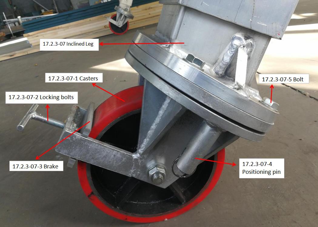
| Item No. | Name | Spec. | Unit | QTY |
|---|---|---|---|---|
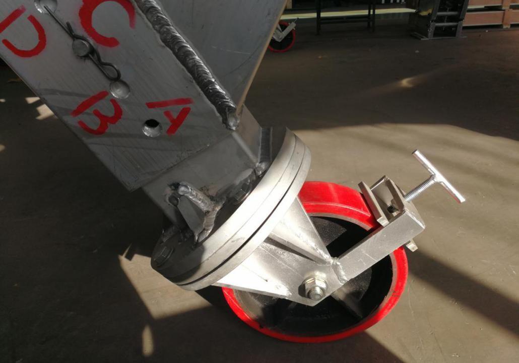
| 17.2.3-07-1 | Casters | Dia. 250mm | Pcs | 4 |
| 17.2.3-07-2 | Locking bolts | Pcs | 4 | |
| 17.2.3-07-3 | Brake | Pcs | 4 | |
| 17.2.3-07-4 | Positioning pin | Pcs | 4 | |
| 17.2.3-07-5 | Bolt | M16*30 | pcs | 16 |
4.3、Platform Assembly
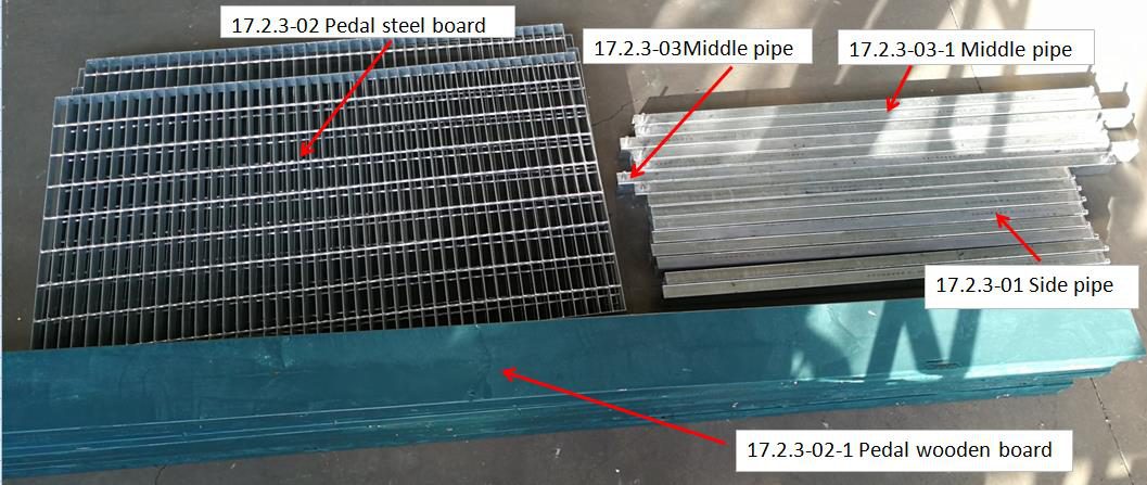
| Item No. | Name | Spec. | Unit | QTY |
|---|---|---|---|---|
| 17.2.3-01 | Side pipe | L=1400mm | Pcs | 8 |
| 17.2.3-02-1 | Pedal | 3000*80*40mm | set | 1 |
| 17.2.3-03 | Middle pipe | L=1640mm | Pcs | 2 |
| 17.2.3-03-1 | Middle pipe | L=1500mm | pcs | 5 |
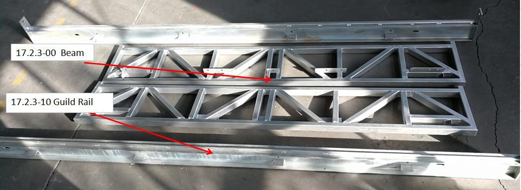
4.4、Beam and Guide Rail Assembly
| Item No. | Name | Spec. | Unit | QTY |
|---|---|---|---|---|
| 17.2.3-00 | Beam | 3000*470mm | Pcs | 2 |
| 17.2.3-10 | Guide Rail | L=4100mm | pcs | 2 |
Move the parts shown above to the construction site and wait for assembly.
4.5、Inclined Leg and Rack Assembly
First, assemble the inclined legs (17.2.3-07) onto the racks (17.2.3-08). Insert the inclined legs into the racks and align the holes as shown in the drawings (Item 10), then secure them with the R-type pins. Install the four casters in the same positions. Pull down the positioning pin and adjust the casters so that they align with the axial direction of the rotary kiln. Wait for the next step.
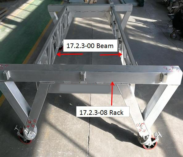
4.6、Rack and Beam Assembly
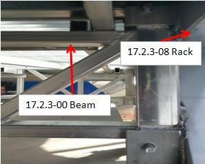
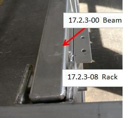
Set the two racks (17.2.3-08) upright with the help of workers, place the beam (17.2.3-00) into the slots on the racks, insert the Ø18 round pins to connect the beams to the racks, then insert the R-type pins into the pin holes to lock them in place. Wait for the next step.
4.7、Arm and Rack Assembly
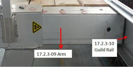
First, connect the arms (17.2.3-09) to the guide rails (17.2.3-10), then insert the telescopic beam into the rack. As shown in the drawings (Item 10), insert the pins into the corresponding holes and secure them with the R-type pins. Install the four arms at the same positions.
4.8、Platform Assembly
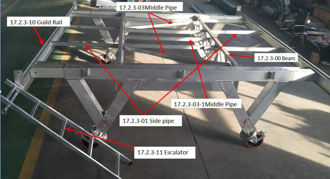
As shown in the picture, install the 2 middle pipes (17.2.3-03) and insert the 5 side pipes (17.2.3-03-1); then insert the side pipes (17.2.3-01). Connect the guide rails (17.2.3-10) to the arms (17.2.3-09) with four M20×30 bolts, and secure the side pipes (17.2.3-01) into the corresponding holes with R-type pins. Hang the access ladder (17.2.3-11) in the corresponding position.
4.9、Laying the Platform Grille Net and Platform Plank
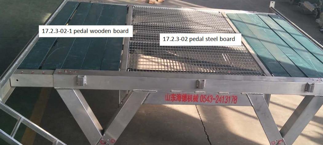
As shown in the picture, lay the pedal (17.2.3-02-1) in place. Wait for the next step.
4.10、Inclined tube Assembly
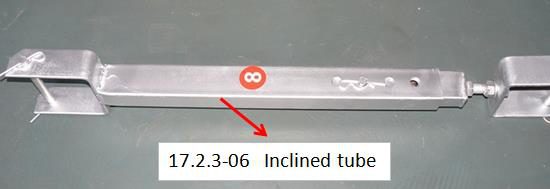
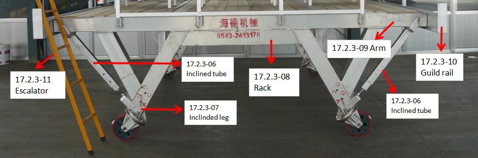
| Item No. | Name | Spec. | Unit | QTY |
|---|---|---|---|---|
| 17.2.3-06 | Inclined tube | L=880mm | pcs | 4 |
Assemble the inclined tubes (17.2.3-06): connect the lower end to the inclined leg (17.2.3-07) and the upper end to the arm (17.2.3-09), securing both ends into the corresponding holes with R-type pins. Then adjust the M20 support bolts to ensure both ends are tightened.
4.11、Arch Frame Components Assembly and Adjustment
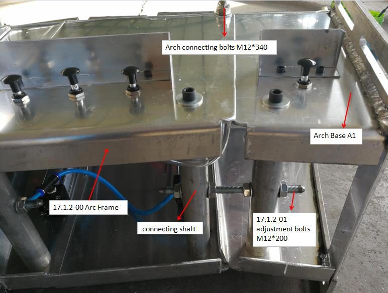
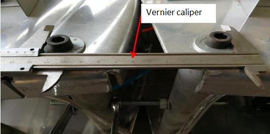
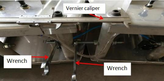
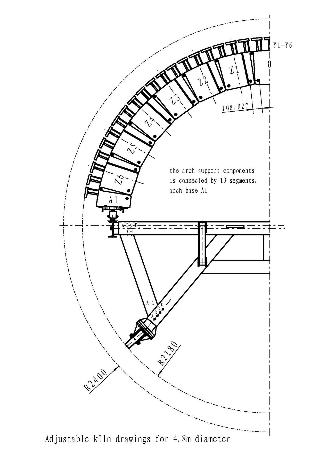
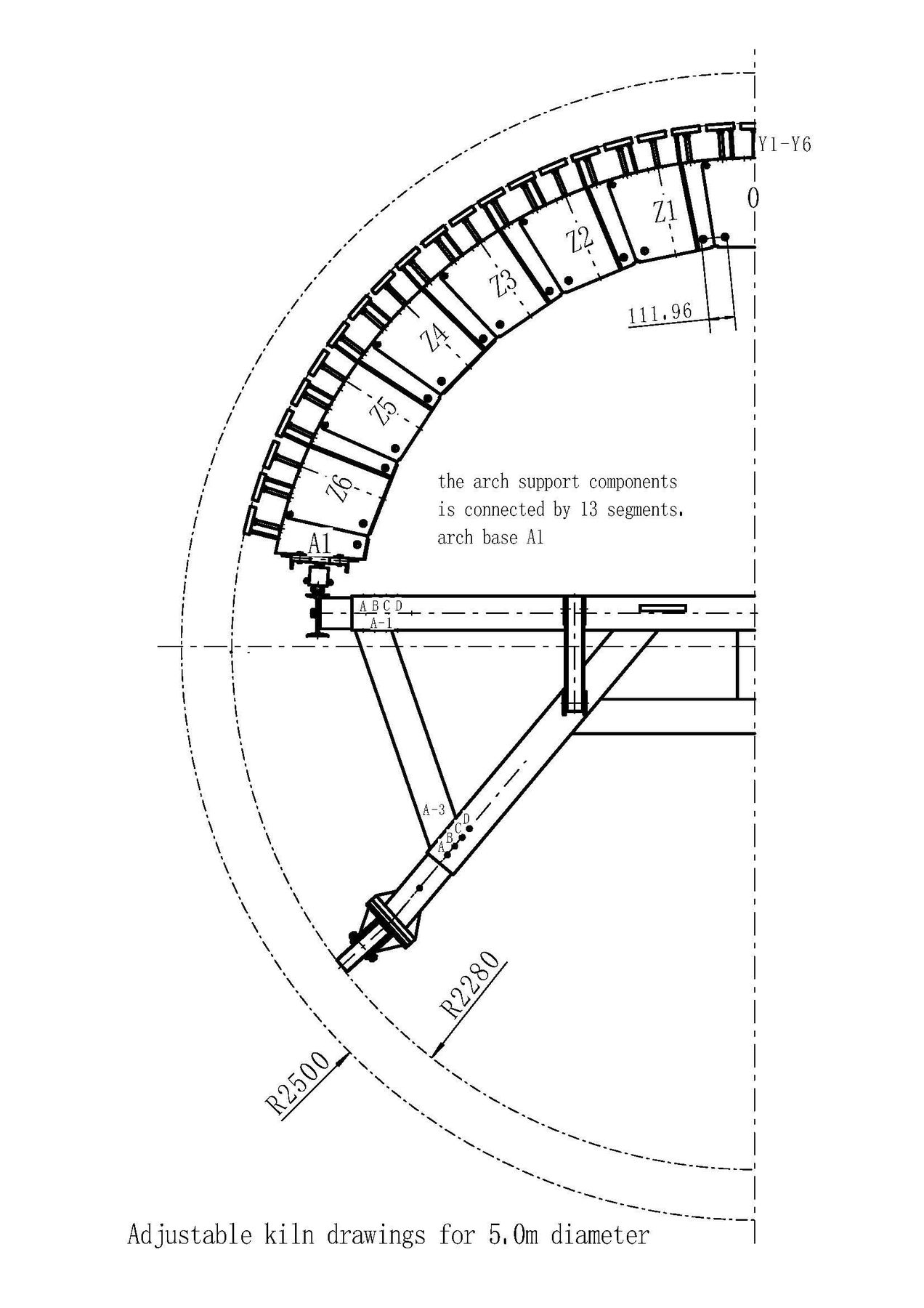
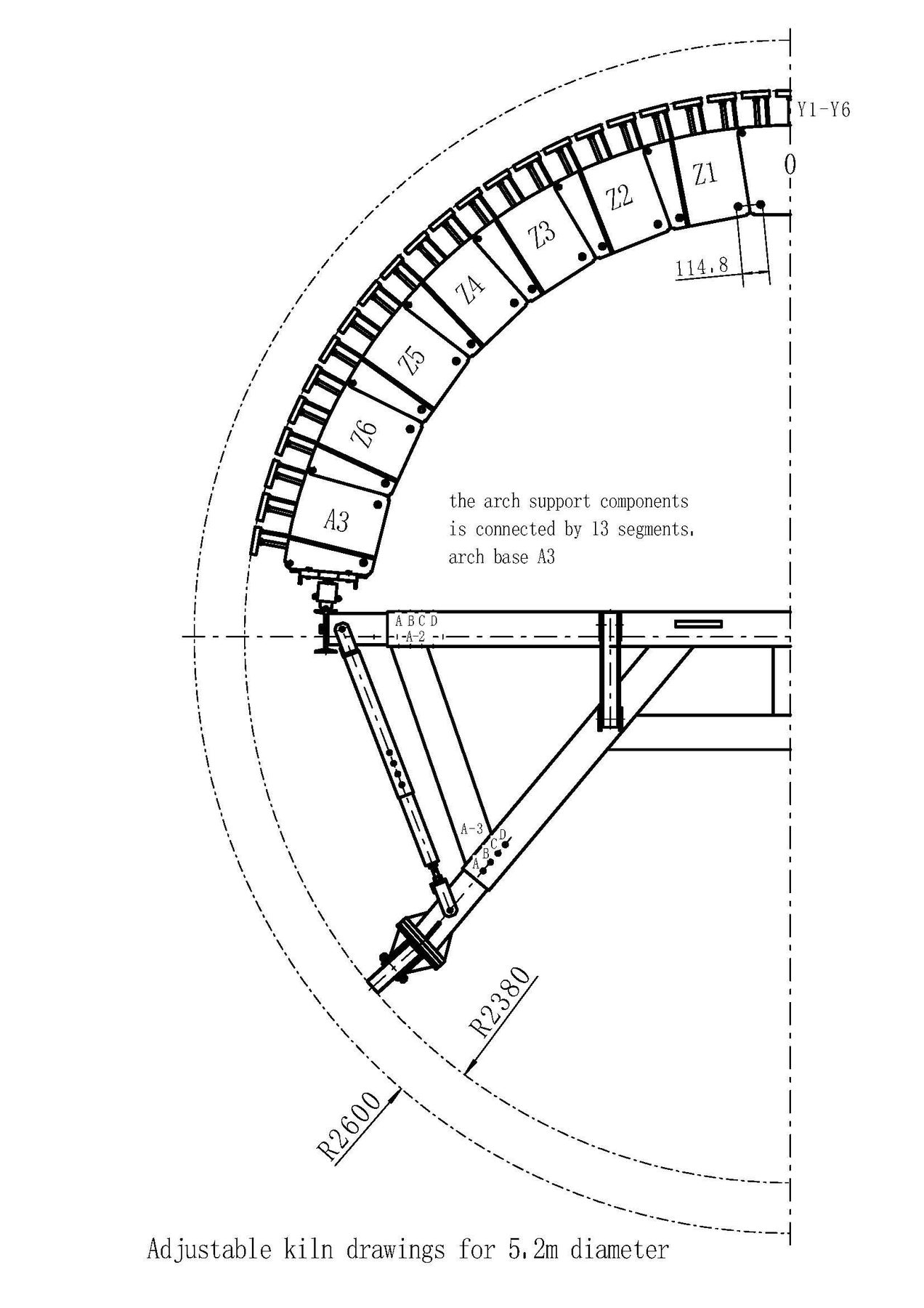
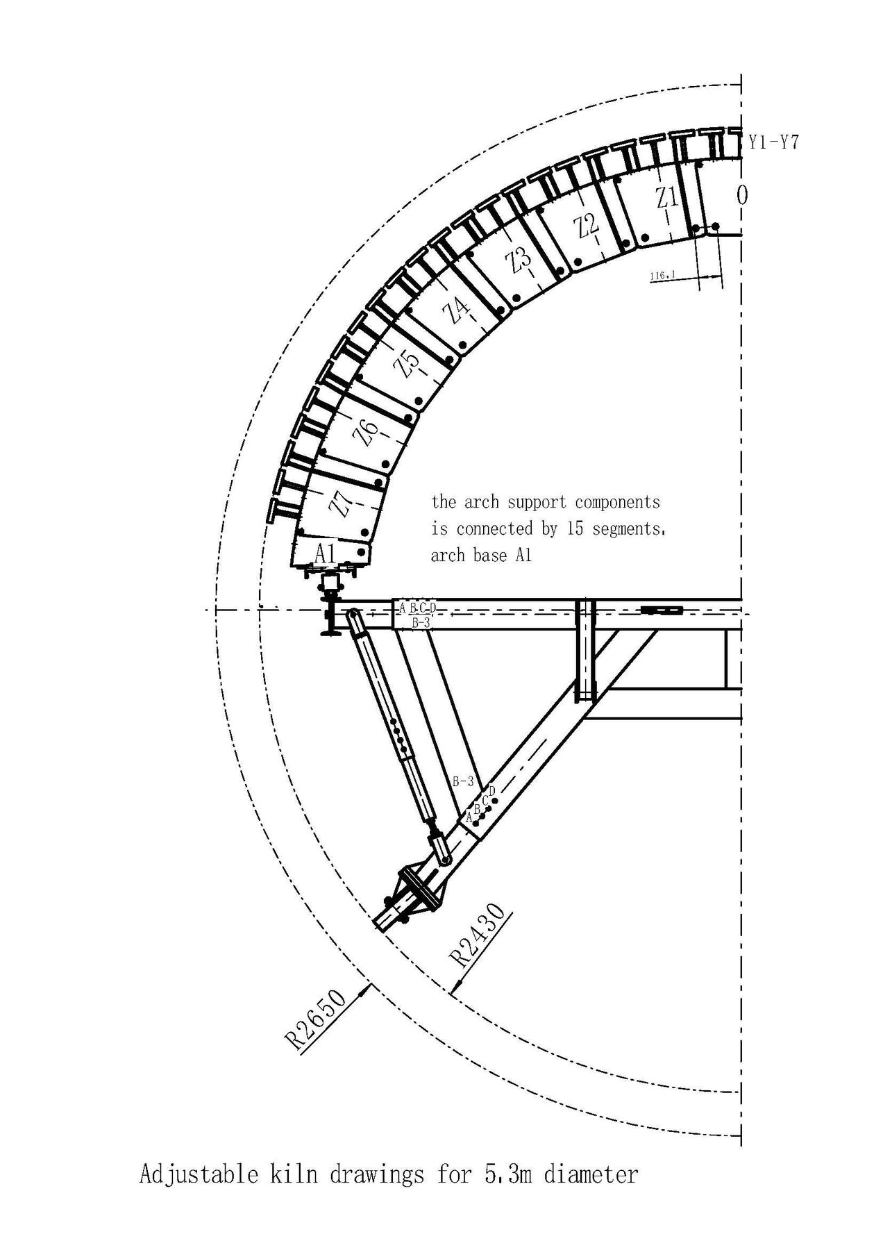
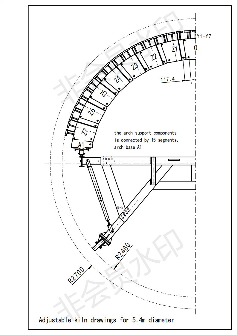
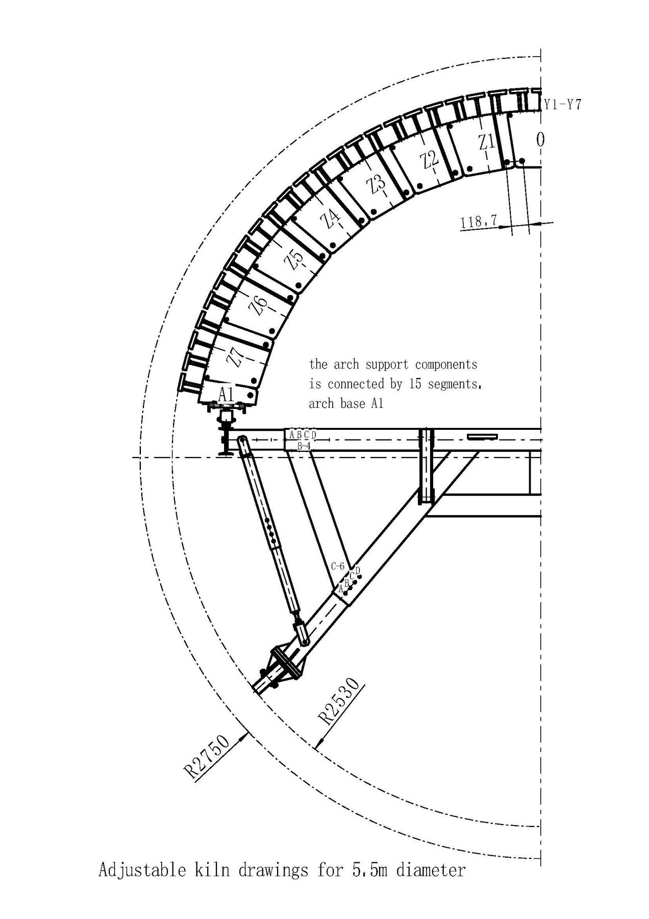
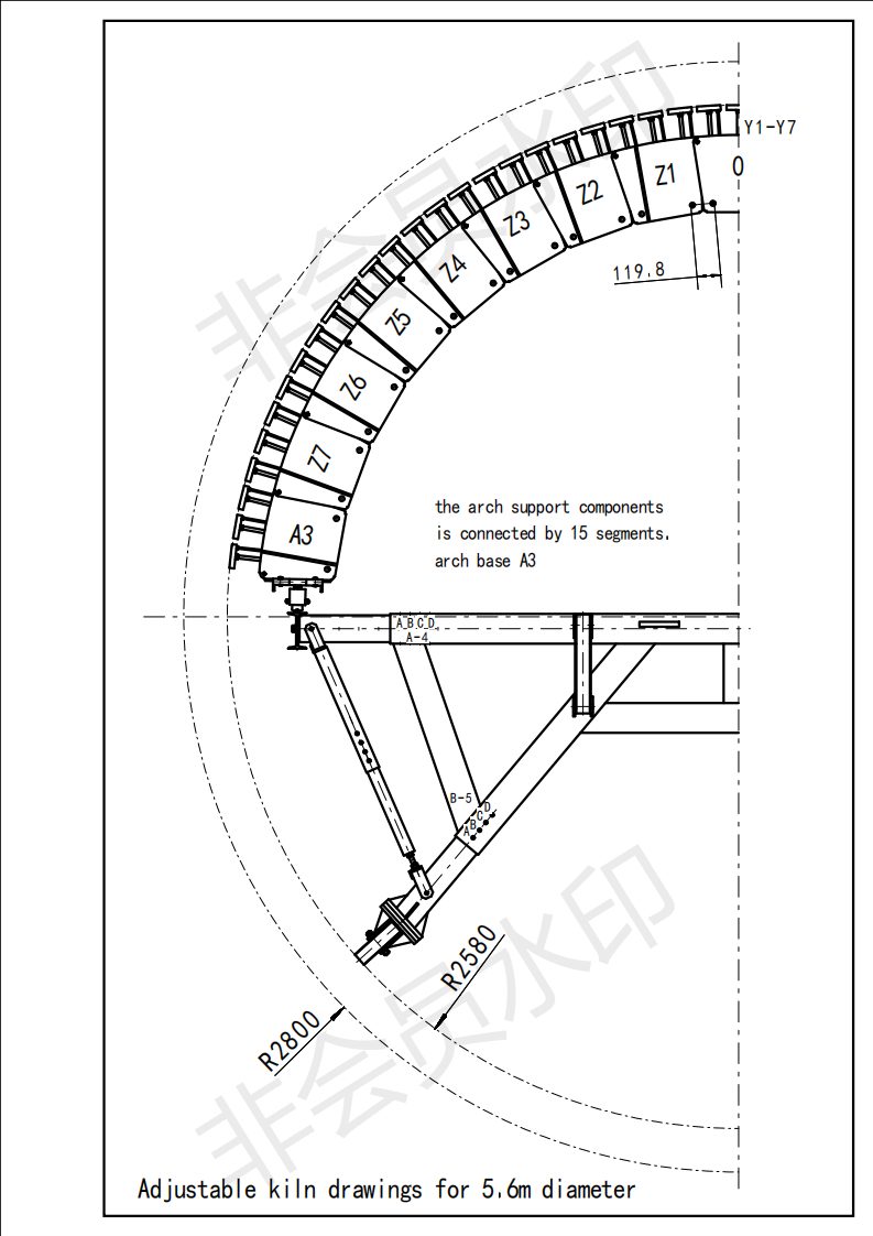
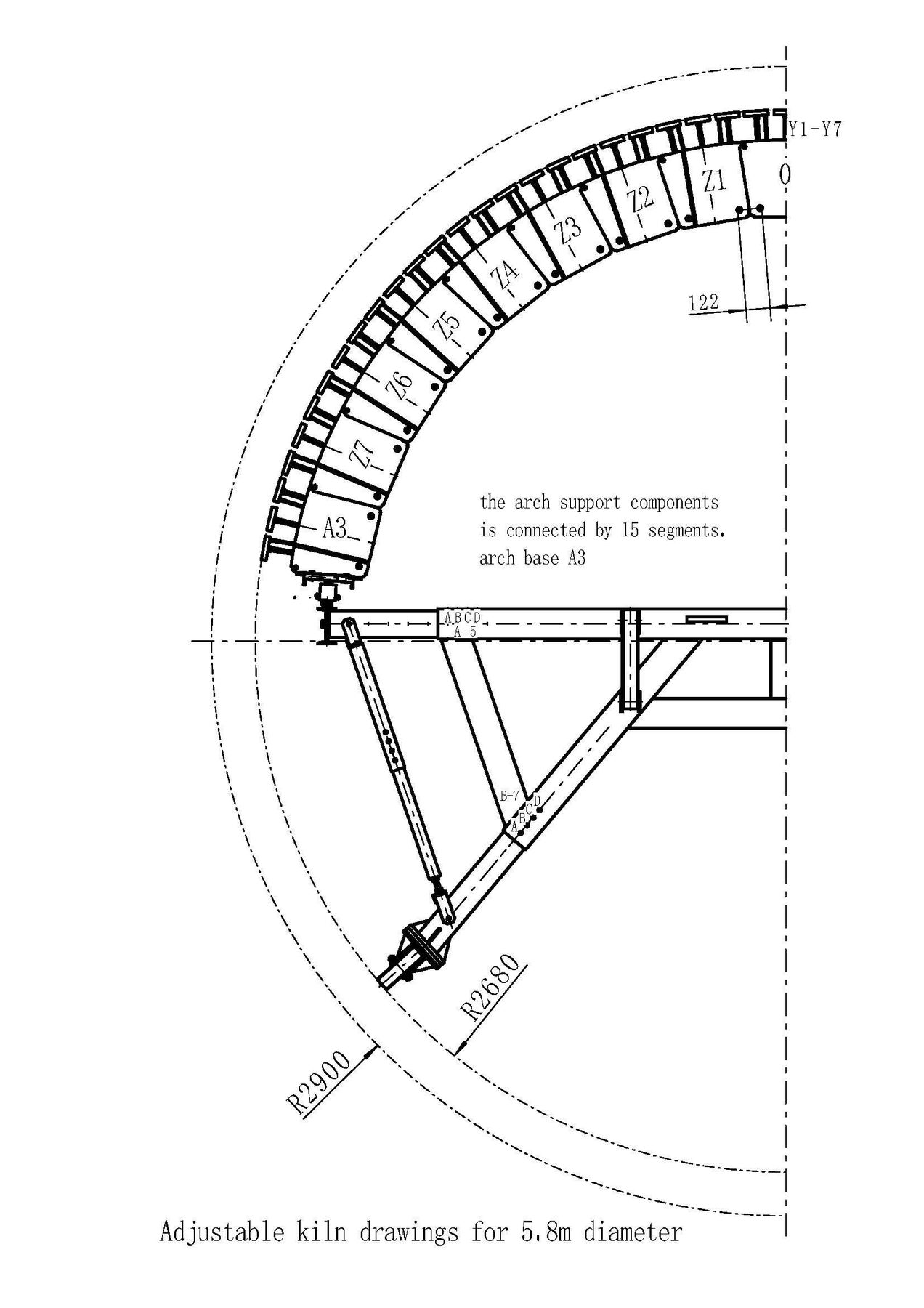
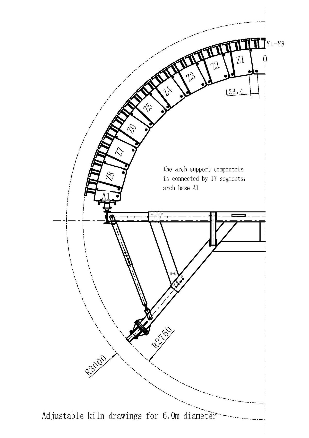
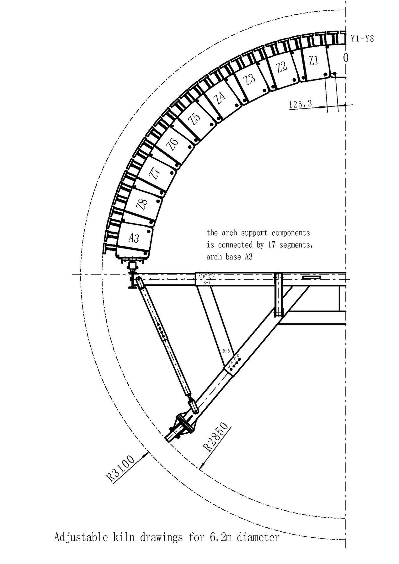
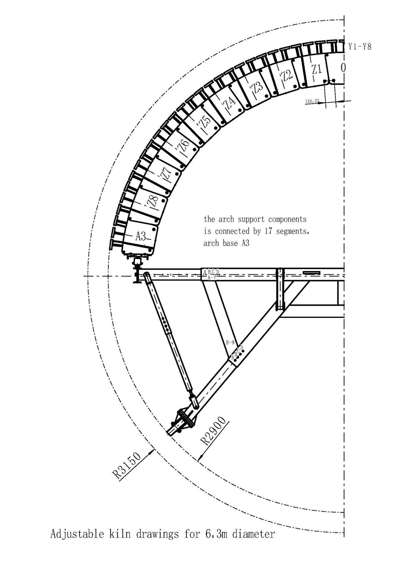
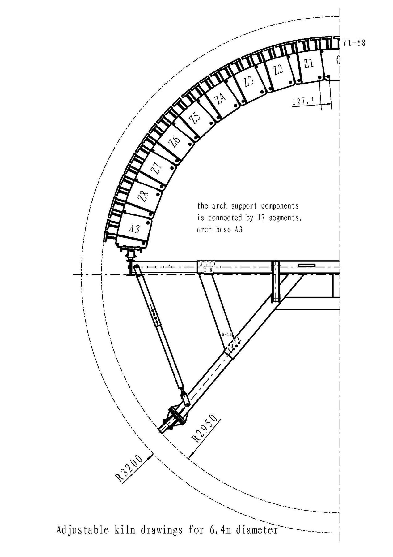
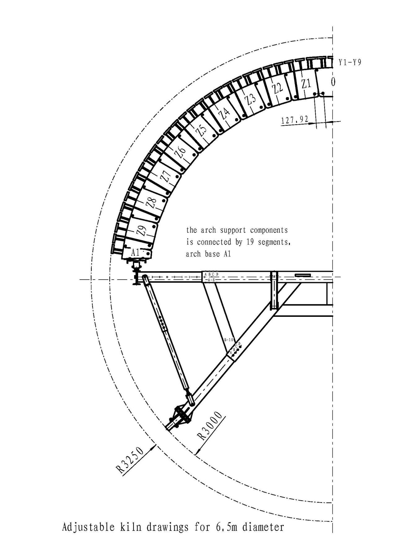
Depending on the kiln diameter, the number of arch support segments can be varied by adding or removing segments on both sides. According to the selected diameter, use the full or half arch base segments (No. A1–A2) as shown in the drawing, and adjust the remaining sections evenly from left to right. Adjust the arch radius using the adjustment bolts (17.1.2-01). Loosen the arch connecting bolts (17.1.2-01 M12*340) with a wrench to the position specified in the Item 10 drawings, then retighten the bolts after adjustment.
4.12、Arch Frame Components
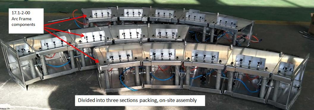
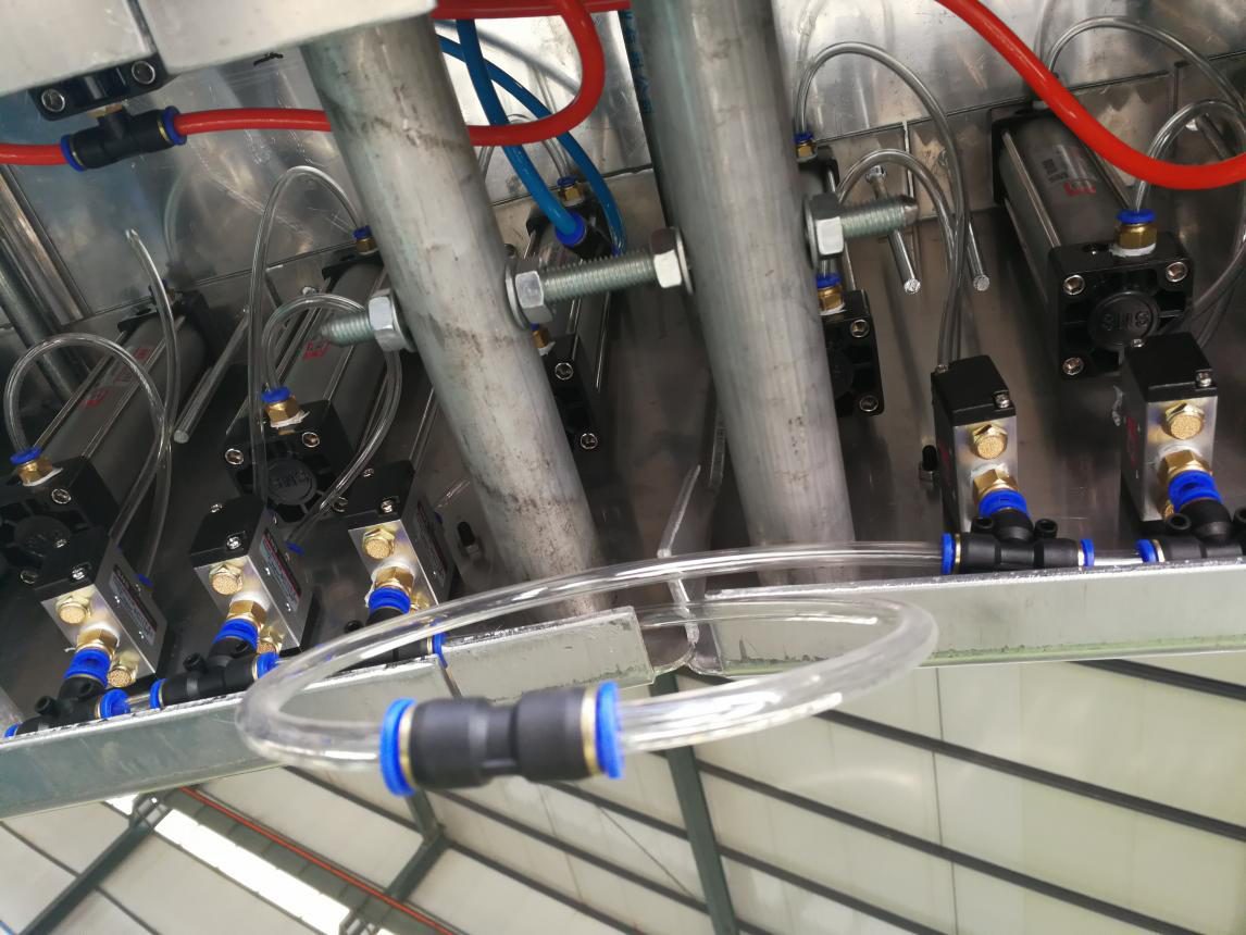
Arch frame components (17.1.2-00): the two middle segments are marked No. "0", and the remaining segments are numbered from the centre — left Z1, 2, 3..., right Y1, 2, 3... The arch base segments are available in No. A1, A2 and A3; their quantity is adjusted according to the kiln diameter as shown in the Item 10 drawings. Connect the three sections together as per Item 4.11, then connect the hoses by colour (blue–blue, red–red, white–white). NOTE: to disconnect a quick-release coupling and its air hose, press the blue collar of the coupling with the forefinger and thumb of one hand and pull the hose out with the other. To connect them, hold the coupling with one hand and push the hose fully into the end with the other. All other couplings are operated in the same way.
4.13、Arch Frame Components Overall Assembly
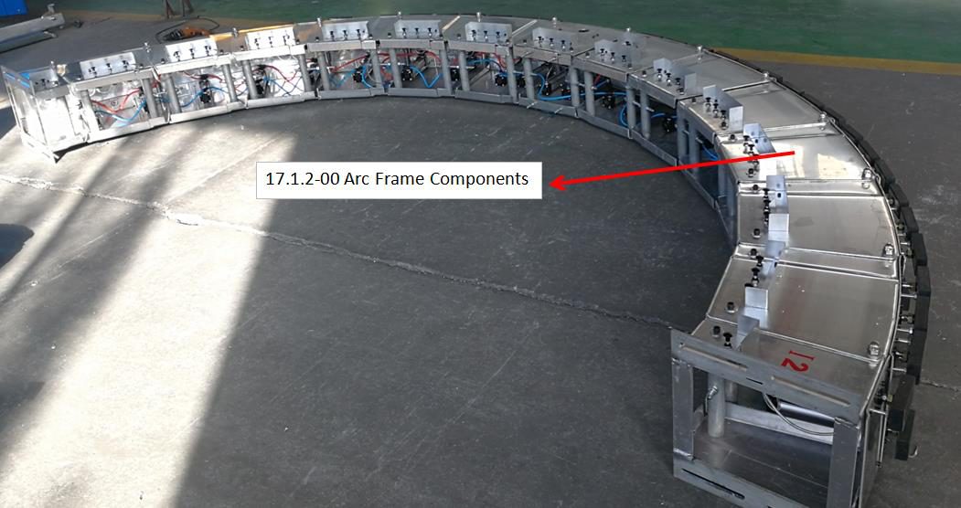
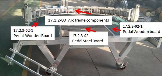
After the arch frame components (17.1.2-00) have been adjusted as per the drawing, move them to the machine platform and assemble the complete arch. Then erect the arch support and connect it to the pulley assembly (17.1.1-00).
4.14、Pulley and Arch Frame Components Assembly
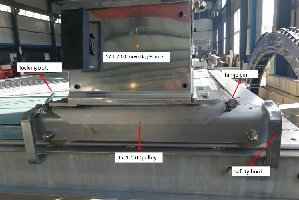
Connect the arch frame components (17.1.2-00) to the pulley assembly (17.1.1-00) with eight M12×30 bolts, and secure the pulley with the pin shaft. Then move the arch frame and check that the pulley runs smoothly on the guide rail.
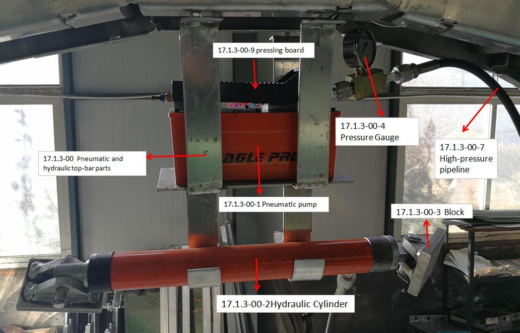
4.15、Pneumatic Pump and Hydraulic Cylinder
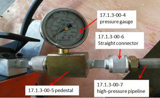
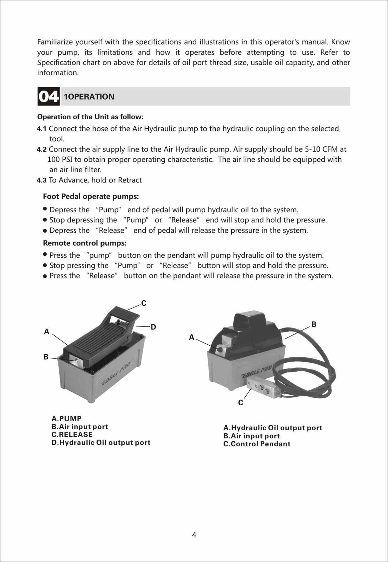
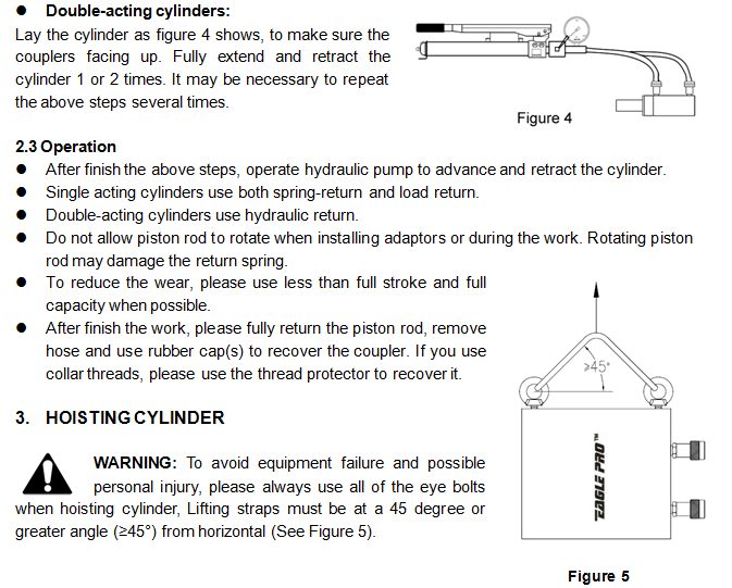
Fully assemble the pneumatic/hydraulic top bar assembly (17.1.3-00), then hang it on the arch frame components (17.1.2-00) and secure it with the M8 bolts. Pneumatic pump operation: press down the right side of the pressing board (17.1.3-00-9) and the pump starts working, delivering hydraulic oil to the hydraulic cylinder. The cylinder extends as the oil volume increases until the refractory bricks on both sides are tightened, then stop pressing. To release the pressure, lift the pressing board (17.1.3-00-9); the hydraulic oil returns to the tank and the pressure is relieved. Shell S2 V 46 hydraulic oil is recommended, and the working pressure of the pneumatic hydraulic pump is 0–30 MPa.
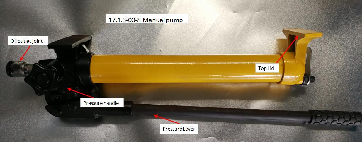
Manual pump (spare): remove the top lid before use and fill with hydraulic oil (Shell S2 V 46). Connect the outlet coupling to the hydraulic cylinder hose. Tighten the pressure handle clockwise and pump the handle up and down. When the pressure gauge pointer reaches the required pressure, stop. Then turn the pressure handle counter-clockwise to release it, and the hydraulic oil returns to the tank. Repeat this procedure for each use.
| Item No. | Name | Spec. | Unit | QTY |
|---|---|---|---|---|
| 17.1.3-00 | Pneumatic and hydraulic top-bar parts | EC002/ES1014 | Group | 1 |
| 17.1.3-00-1 | Pneumatic Pump | EC002 | Pcs | 1 |
| 17.1.3-00-2 | Hydraulic Cylinder | ES1014 | Pcs | 1 |
| 17.1.3-00-3 | Block | 120x50mm | Pcs | 2 |
| 17.1.3-00-4 | Pressure Gauge | 60MPa | Pcs | 1 |
| 17.1.3-00-5 | Pedestal | Pcs | 1 | |
| 17.1.3-00-6 | Straight connector | M24*1.5 | Pcs | 3 |
| 17.1.3-00-7 | High pressure pipeline | 2M | Pcs | 1 |
| 17.1.3-00-8 | Manual Pump | Spare | Set | 1 |
| 17.1.3-00-9 | Pressing board | pcs | 1 |
4.16、Main air supply installation location
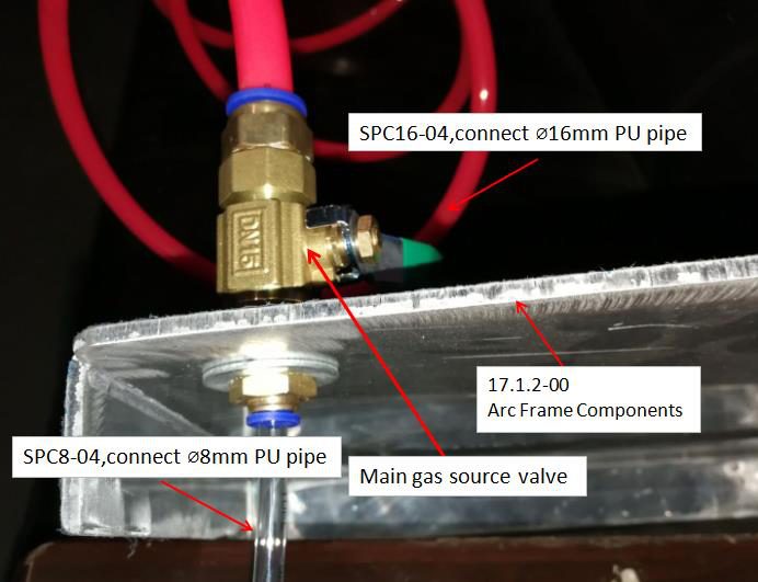
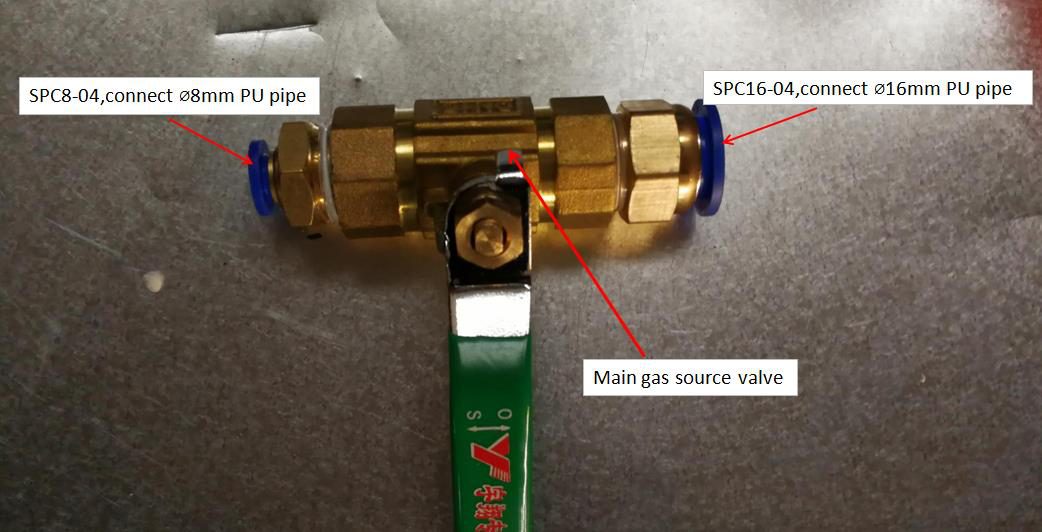
Install the main air supply valve in the air inlet on the arch frame components (17.1.2-00). Connect one side to the air compressor hose with Ø16 mm PU tubing, and the other side to the non-return valve in the machine with Ø8 mm PU tubing.
4.17、Whole machine assembly drawing
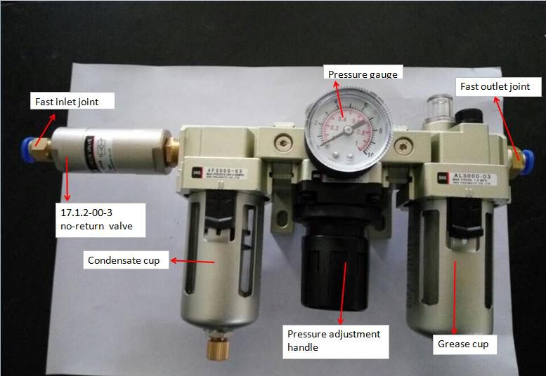
4.18、Schematic diagram of the oil–water separator (17.1.2-00-1)
Oil–water separator operation: once the air supply is connected, the pressure is shown on the pressure gauge. Pull down the pressure regulating handle; turn it clockwise to increase the pressure and counter-clockwise to reduce it. After setting the required pressure, push the handle up to lock it.
The condensate cup can be drained manually or automatically. For manual draining, push up the drain valve under the condensate cup and the water will be discharged. When the equipment is not in use and the pressure has dropped, the drain valve opens automatically to discharge any condensate.
Filling lubricating oil: remove the plug from the oil filler and add oil through the filler.
Oil feed adjustment: turn clockwise to reduce the oil feed and counter-clockwise to increase it. The oil feed rate can be observed through the sight window on the cup.
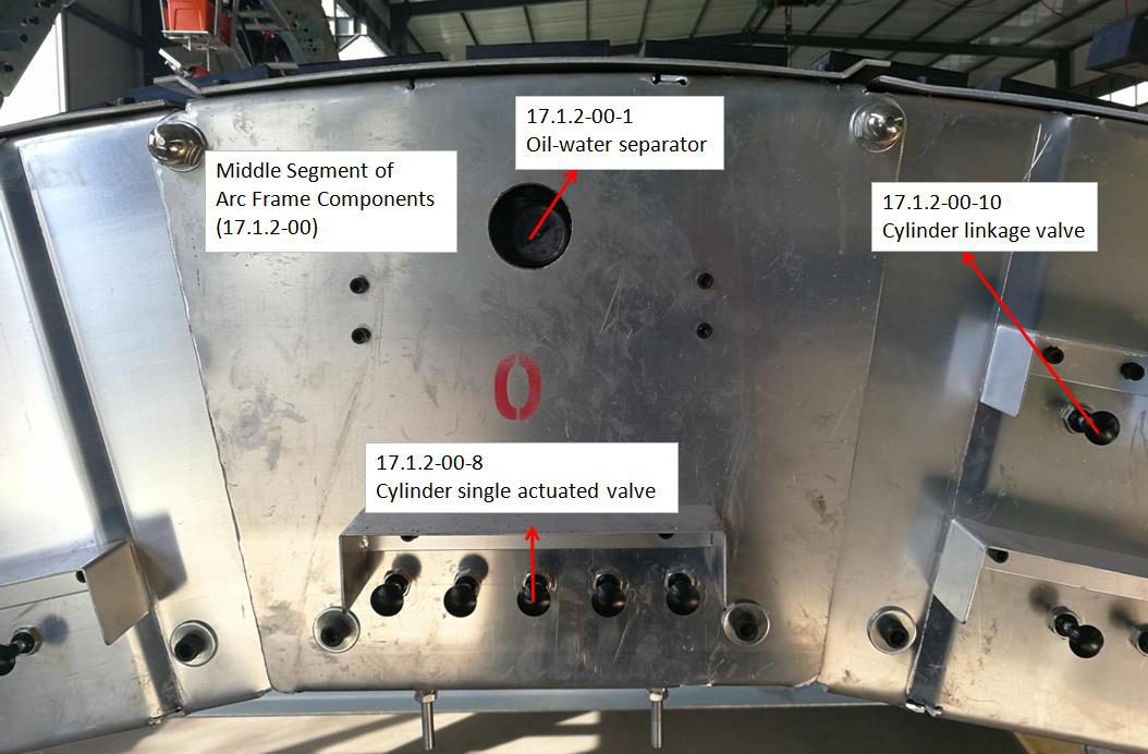
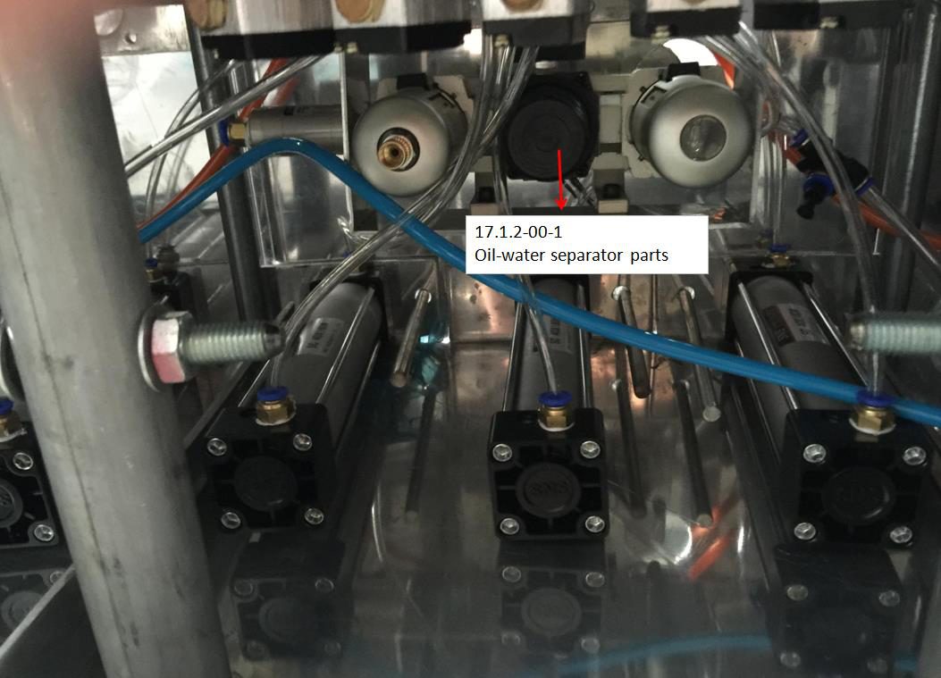
| Item No. | Name | Spec. | Unit | QTY |
|---|---|---|---|---|
| 17.1.2-00-1 | Oil–water separator | AC3000 | Pcs | 1 |
| 17.1.2-00-2 | Pressure Gauge | 1MPa | Pcs | 1 |
| 17.1.2-00-3 | Non-return valve | Lcv-08 | Pcs | 1 |
| 17.1.2-00-4 | Straight connector | SPC8-02/03 | pcs | 2 |
4.19、Main parts location diagram
| Item No. | Name | Spec. | Unit | QTY |
|---|---|---|---|---|
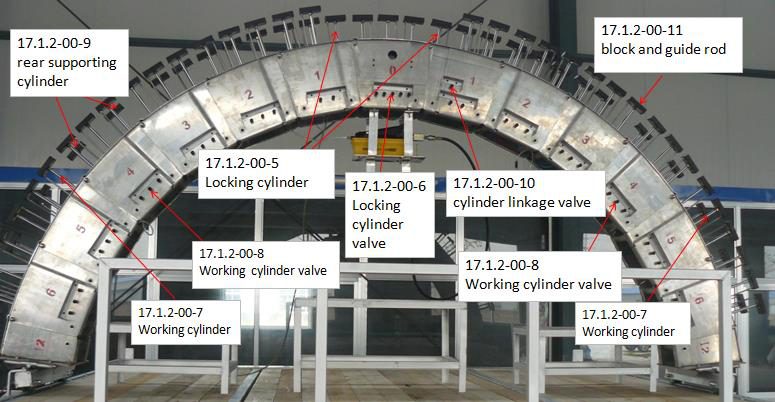
| 17.1.2-00-5 | Locking Cylinder | SC40*150 | Pcs | 5 |
| 17.1.2-00-6 | Locking Cylinder Valve | 4R210-08 | Pcs | 5 |
| 17.1.2-00-7 | Working Cylinder | SC40*150 | Group | 1 |
| 17.1.2-00-8 | Working Cylinder Valve | SC40*150 | Group | 1 |
| 17.1.2-00-9 | Rear supporting Cylinder | SC40*150 | Group | 1 |
| 17.1.2-00-10 | Cylinder Linkage Valve | 4R210-08 | Group | 1 |
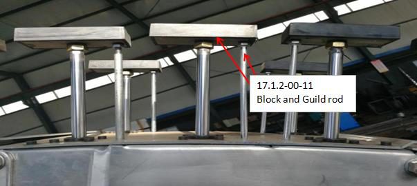
| 17.1.2-00-11 | Block and guide rod | 120*50/M8 | Group | 1 |
Inspection / Daily ChecksInspection / Daily Checks
| No. | Work to be done | Frequency | Remarks |
|---|---|---|---|
| 1 | Cleaning the machine | After each use | |
| 2 | Check the middle segments marked No. "0" (see Item 10 drawing) and the oil–water separator (17.1.2-00-1). Check that the oil level is correct and top it up if low. | Before every use of the device | Use commercially available pneumatic oil, viscosity 2.5 °E at 50 °C. Do not use hydraulic oil! |
| 3 | Check the air pressure on the pressure gauge (17.1.3-00-4). It should be between min. 5 bar and max. 7 bar. | Before debugging or temporarily working | Pressure must be adjusted either at the external air supply or via the adjusting handle on the oil–water separator. |
| 4 | Check the pneumatic system for leaks: retract all cylinders, disconnect the external air supply, and measure how long the pressure takes to drop by 2.5 bar on the oil–water separator pressure gauge. Then repeat the test with the cylinders. | Before each use, depending on usage frequency | A 2.5 bar pressure drop should take at least 30 minutes. If it takes less than 30 minutes, check all cylinders and hose connections for leaks and replace them if necessary. |
| 5 | Press all cylinders and check their movement. | Before every use of the device | Replace cylinders if necessary |
| 6 | Run a smoothness test of the pulley on the guide rail. | Before every use of the device | Lubricate the bearings if necessary |
| 7 | Check the casters and the general condition of the rubber coating. | Before every use of the device | If the rubber coating is badly damaged, replace it if necessary. |
| 8 | Check the hydraulic cylinder, hose and hydraulic manual pump | Before every use of the device | Extend the cylinder fully by manual operation. If full extension is not possible, remove the top lid of the manual pump and refill with hydraulic oil. |
MasonryMasonry
6.1、First, connect the air supply and wait until the pressure gauge on the oil–water separator (17.1.2-00-1) reaches the rated pressure (0.4–0.6 MPa); then begin the trial run.
6.2、Place the refractory bricks in position. Press the single-acting cylinder valves (17.1.2-00-8) one by one to release the locking position and press the jacks against the refractory bricks from both sides. When the required pressure is reached (30 MPa on the hydraulic gauge), release the single-acting cylinder valves one by one to ensure all cylinders are reset.
6.3、Confirm that the jack is pressed tight, then move the pulley so that the blocks on the rear supporting cylinders advance by one brick length (230 mm), in line with the jack position. Then press the cylinder linkage valve (17.1.2-00-10) so that the rear blocks on the arch support components press against the fire bricks. After confirming that the blocks on both sides are in place, release the pressing board (17.1.3-00-9) on the pneumatic pump, remove the jack and move away. Then use the four middle locking cylinders (17.1.2-00-6) to build up and reinforce the ring with the steel plate.
After confirming that the fire bricks are held tightly in the locking position, actuate the cylinder linkage valve so that the blocks on the arch support components reset. At the same time, repeat the cycle for the next row as per item 6.2.
6.4、The QZJ10KT-1 machine must be adjusted to suit the inner diameter of the kiln: adjust the inclined leg length in the vertical direction and the arm length in the lateral direction, and adjust the arch diameter using the arch adjusting bolts.
TroubleTrouble
| Disorder | Possible Cause | Elimination |
|---|---|---|
| Device does not fit the kiln | •Aluminium arms connected at the wrong hole positions •Aluminium inclined legs connected at the wrong hole positions |
•Check the corresponding setting sheet in the documentation. The diameters given on the setting sheet are the inner bricking diameters. |
| External air pressure supply interrupted while working with the device | •Power failure •Faulty cable •Faulty compressor |
•Check the power supply and cable •Check the air compressor; replace it if necessary |
| Insufficient cylinder force on the arch frame | •External air supply pressure below 5 bar •Air pressure fault at the oil–water separator •Leakage in the pneumatic system •Kinked hose |
•Check the pressure supply •Adjust the oil–water separator •Check for leaks; replace cylinders, valves or hose connections if necessary |
| Disorder | Possible Cause | Elimination |
|---|---|---|
| Insufficient pressure in the pneumatic cylinders on the segmented arch | •Bent guide rod •Bent piston rod •Mechanically jammed valve •Defective screw connection •Excessive contamination |
•Replace the guide rod •Replace the cylinder •Replace the valve •Replace the screw connection •Clean the system thoroughly |
| Pneumatic cylinders operate extremely slowly | •Defective air supply line •Compressor airflow rate too low •Kinked air supply line •Defective pneumatic valve |
•Replace the air supply line •Check the compressor •Check the air supply hoses •Replace the pneumatic valve |
| When a valve is actuated, one row of cylinders moves up while the others move in the opposite direction | Quick-release couplings connected in the wrong order (1-2, 3-4, 5-6, etc.) | •Swap the quick-release couplings •Check the hoses and colour coding (blue–blue, red–red, white–white) |
| Too much or too little lubricating oil fed to the compressor | Oil feed not adjusted correctly at the oil–water separator | •Ensure the oil feed is adequate •Turn clockwise to reduce the oil feed and counter-clockwise to increase it |
| Hydraulic cylinder does not extend fully or is stuck | Low oil level in the cylinder | •Inspect the cylinder according to the hydraulic cylinder operating instructions |
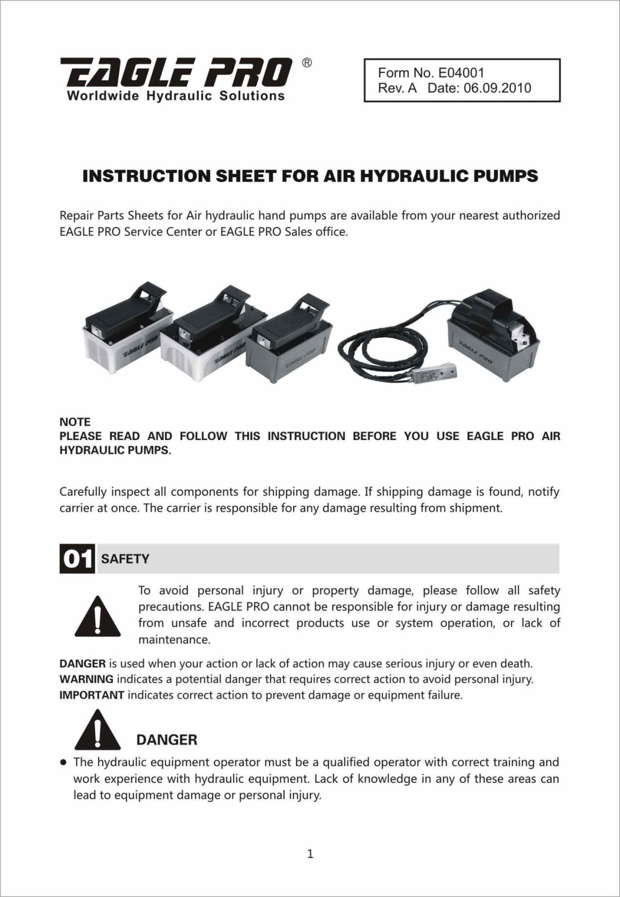
| Pneumatic pump does not operate | •Input air pressure too low •Insufficient oil in the pump |
•Top up the oil level if necessary •Check the air pressure at the external supply (see the pneumatic pump operating instructions, P34–38) |
Disassembly and StorageDisassembly & Storage
Disassemble the machine in the reverse order of the assembly steps. After disassembly, clean all debris from the machine surfaces. Seal every pneumatic connector to prevent dust from entering the lines. Store the pins and bolts of the connecting parts in the tool box, and place the remaining parts in the warehouse.
Maintenance and lubricationMaintenance
9.1、Check and tighten all fasteners and connecting parts of the equipment before each use.
9.2、Check the oil level of the oil–water separator before each use and top it up in time if it is below the required level (Shell S2 V 46).
9.3、After use, disassemble the equipment in the reverse order of installation, clean it, and place it in the packing box.
- Before the fire bricks are confirmed to be held tightly by the jacks in the locking position, it is strictly prohibited to reset the cylinder linkage valve.
- The working pressure of the pneumatic pump must not exceed 30 MPa.
- The machine is equipped with a manual pump; use it when a short stop is expected.
- The load on the frame must not exceed 3 tonnes.
DrawingsDrawings
| No. | Type | Drawing Name |
|---|---|---|
| 1 | QZJ10KT-1 | Commissioning Chart |
| 2 | QZJ10KT-1 | Assembly Drawing |
The complete drawing sheets are reproduced below. Click any sheet to view it enlarged.
Safety measures during standard operationSafety & Environmental Protection Precautions
- All safety devices and equipment must be in place and functional before the machine is operated.
- Before starting the machine, the operator must make sure that nobody is at risk of injury.
- After use, check that all safety devices and equipment are still functional.
- During cleaning or maintenance, the machine must be stopped and the power turned off.
- After cleaning or maintenance is complete, reinstall all safety devices and equipment.
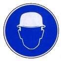
HELMETS
Protective helmets must be worn in this area. Failure to comply can result in serious head injury.

EYE PROTECTION
Eye protection must be worn at all times. Failure to follow this instruction can result in serious eye injury.
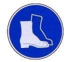
SAFETY FOOTWEAR
Worker safety footwear must be worn at all times. Failure to comply with this requirement may result in serious foot injuries.

PROTECTIVE GLOVES
Wear protective gloves when working with hot parts on or near the machine.
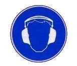
EARS PROTECTION
Ear protection must be worn in this area. Failure to comply can result in serious hearing loss.
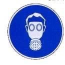
WEAR PROTECTIVE MASK
Protective masks must be worn. Failure to comply may result in breathing difficulties.

WASTE
Used oil is harmful to the environment and to health. It must be disposed of in accordance with local regulations and the manufacturer's instructions.
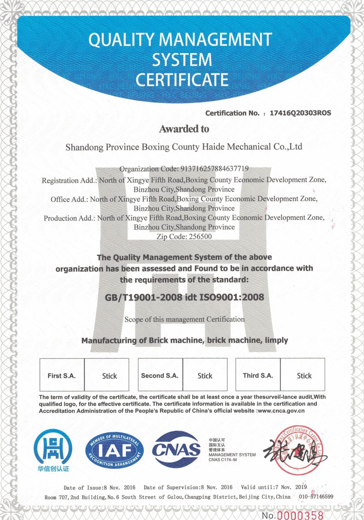
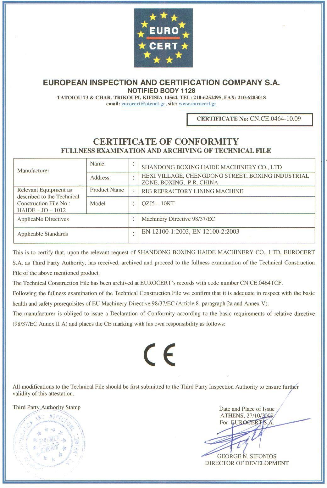
Warranty &CertificateWarranty & Certificate
Main parts and spare parts are covered by a 1-year quality warranty against non-man-made damage, counted from the bill of lading date.
After-sales ServiceAfter-sales Service
- (1) Service purpose: fast, decisive, accurate, thoughtful and thorough
- (2) Service objective: win customer satisfaction through service quality
- (3) Service principle: the product warranty period is 12 months. During the warranty period, the supplier repairs or replaces, free of charge, parts damaged due to quality issues. For parts damaged outside the warranty period, only the cost of the accessories is charged.
For damage caused by improper use on the customer's side, the supplier will repair the equipment or supply accessories at cost, and will provide long-term parts supply.
Tel: +86-13455766111 Mr. Ma
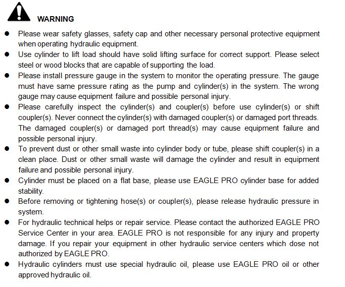
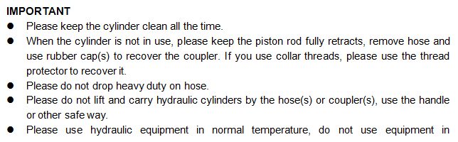
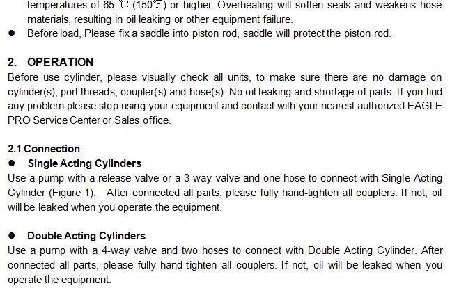
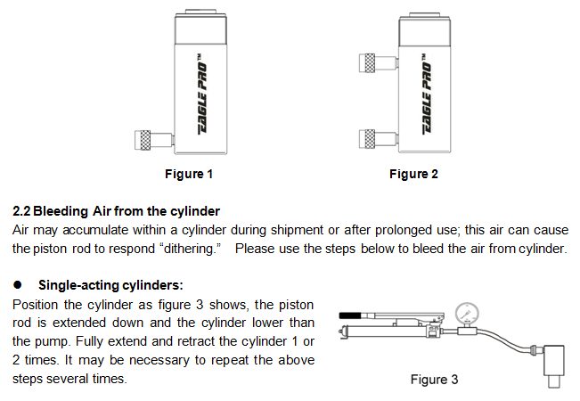
Instructions for the Hydraulic Pump, Hydraulic Cylinder and Air CompressorInstructions for the Hydraulic Pump, Hydraulic Cylinder and Air Compressor
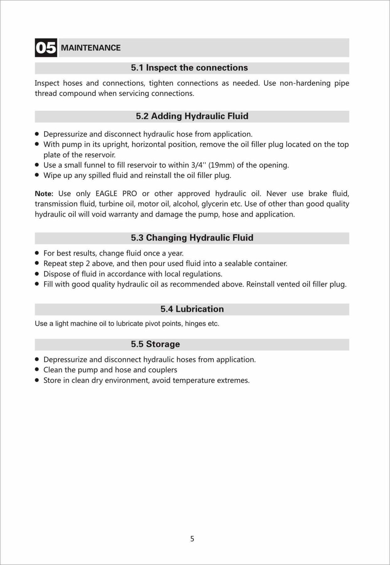
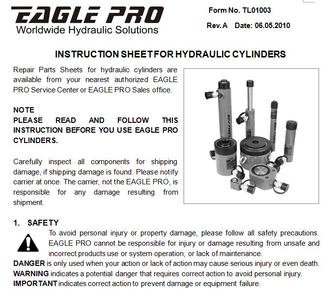
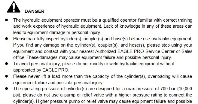
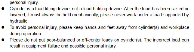
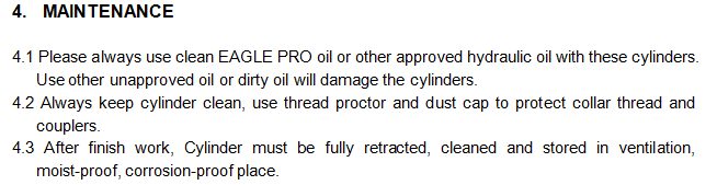
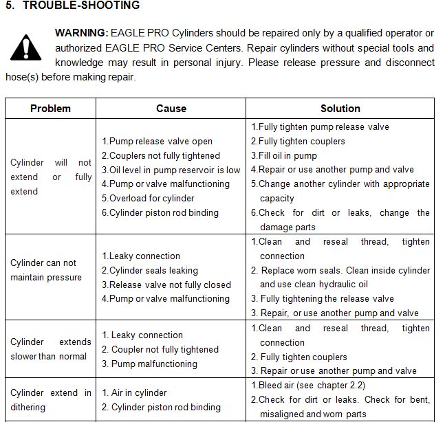
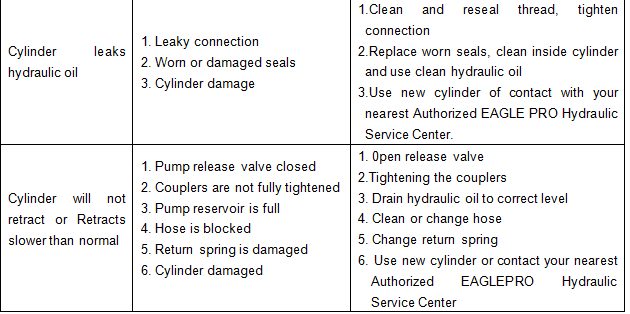
The instruction pages for the pneumatic pump, hydraulic cylinder and air compressor are reproduced below. Click any page to view it enlarged.
Air compressor manual
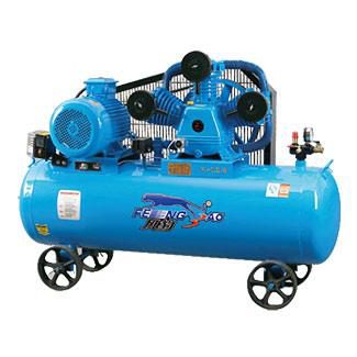
| Type | Input power | Speed | Discharge rate | Max. Pressure | Pressure accumulate | N.W. (KG) | Size (cm) |
|---|---|---|---|---|---|---|---|
| W-0.90/8/HM | 7.5 KW / 10 HP | 950 R.P.M | 900 L/min (31.8 C.F.M) | 8 Bar (115 Psi) | 170 L (44.9 Gal) | 193 | 143×57×100 |
The outlet joint connects to SPC16-04; connect with Ø16 mm PU tubing and configure the 1/2" pipe thread interface.